555 Timer Internal Schematic / 555 Input Impedance Electrical Engineering Stack Exchange : Today we're going to discuss about 555 timer ic or ne555.
byAdmin•
0
555 Timer Internal Schematic / 555 Input Impedance Electrical Engineering Stack Exchange : Today we're going to discuss about 555 timer ic or ne555.. 555 timer internal schematic questions thread starter jearls74; With this information you will learn how how the 555 works and will have the experience to build some of the circuits below. Ⅲ 555 timer internal structure. 500ms is the same as saying 0.5s so by rearranging the formula above, we get the calculated value for the resistor, r as: The three resistors used in it are of 5kohm and they served as a voltage divider between vcc and ground.
Monostable 555 timer circuits will automatically trigger and start a timing cycle when power is applied to the circuit. The 555 timer internal circuit diagram is shown below: The 555 timer is a chip that can be us… It is very common and mostly used ic in various circuits and schematics. Circuits into the ever increasing ranks of timer users.
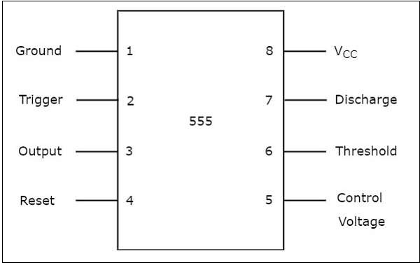
555 Timer Tutorialspoint from www.tutorialspoint.com The image shown below represents the internal schematic of a standard ic 555. In this circuit, we have four basic blocks, these are 1. 555 timer ics need dc voltage in order to operate. The ic 555 is consists of a timer circuit and the timer circuit contains three five kiloohm resistors, for this reason, the name of the ic is ic555.here the block diagram of 8 pin dip package ic 555 is given below. As its wide range of usability and compatibility, also its more range of operating voltage and various other feature makes it ideal for wider use. The 555 timer has two basic operational modes: You can find here some circuits based on 5555 ic. In this section, we will see the working of each internal component of the 555 timer ic.
The 555 timer ic is an integrated circuit (chip) used in a variety of timer, internal schematic (bipolar version).
The ic 556 and ic 558 are 14 pins dual timer and 16 pin quad timer versions of the ic 555 respectively. The internal circuit of this 555 timer consists of comparators, flipflops, transistors, resistors, and output stages. Using the 555 timer ic in special or unusual circuits. We can see that it us made up of 21 transistors, 4 diodes, and 15 resistors. Ic 7555 is the cmos version of the 555 ic with same pin configuration and function. The internal block diagram of ic 555, you can see in the below figure the internal circuit has no. 555 timer internal circuit diagram. The 555 timer internal circuit diagram is shown below: In this video, the brief introduction to the 555 timer ic has been given and the pin diagram (of 8 pin dip 555 ic) and the internal block diagram of the 555. The 555 ic timer circuit above shows a very straightforward design where the ic 555 forms the central regarding the timer, since the 555 timing capacitor is the main component that determines the modified ic 555 toaster circuit. Ic 555 timer is a one of. This tutorial covers different aspects of 555 timer ic and explains its working in Simple 555 timer circuits & projects.
In this circuit, we have four basic blocks, these are 1. The 555 is also very versatile, and can be used. This tutorial provides sample circuits to set up a 555 timer in monostable, astable, and bistable modes as well as an in depth discussion of how the 555 timer works and how to choose components to use with it. Using the 555 timer ic in special or unusual circuits. Additional • timing from microseconds through hours terminals are provided for triggering or resetting if • operates in both astable and monostable modes desired.
Astable Multivibrator Using 555 Timer Sverige Energy from sverige.energy This tutorial provides sample circuits to set up a 555 timer in monostable, astable, and bistable modes as well as an in depth discussion of how the 555 timer works and how to choose components to use with it. Start date nov 11, 2009; An external capacitor is repeatedly charged and discharged to produce the oscillation. You can find here some circuits based on 5555 ic. The 555 timer is a simple integrated circuit that can be used to make many different electronic circuits. Simple 555 timer circuits & projects. There are a lot of applications of this ic, mostly used as vibrators like, astable multivibrator, monostable multivibrator, and bistable multivibrator. This article covers every basic aspect of 555 timer ic.
Ic 7555 is the cmos version of the 555 ic with same pin configuration and function.
555 timer internal circuit operation. The 555 timer is a simple integrated circuit that can be used to make many different electronic circuits. Start date nov 11, 2009; The three resistors used in it are of 5kohm and they served as a voltage divider between vcc and ground. The circuit latches in either the q state or its refer block diagram of 555 timer ic given above: Ic 555 timer is a one of. The 555 timer has two basic operational modes: 555 timer is an industrial standard ic existing from early days of ic. The timer's internal circuitry is largely responsible for this triggering but it is also caused stray or installed capacitance at the trigger input of the timer. This is the pin which connects to the dc voltage to power the 555 chip. The ic 556 and ic 558 are 14 pins dual timer and 16 pin quad timer versions of the ic 555 respectively. In this video, i've explained 555 timer ic with the pin diagram and the internal circuit diagram. This tutorial covers different aspects of 555 timer ic and explains its working in
The ic 556 and ic 558 are 14 pins dual timer and 16 pin quad timer versions of the ic 555 respectively. This is the pin which connects to the dc voltage to power the 555 chip. 555 internal circuit consists of three series 5k resistors connected between the vcc and gnd. The 555 timer is a chip that can be us… 555 timer internal circuit diagram.
Pin On Electronics from i.pinimg.com In this video, the brief introduction to the 555 timer ic has been given and the pin diagram (of 8 pin dip 555 ic) and the internal block diagram of the 555. Circuits into the ever increasing ranks of timer users. Being an integral part of electronics project, 555 timer ic is very often used in simple to complex electronics projects. The image shown below represents the internal schematic of a standard ic 555. The internal block diagram of ic 555, you can see in the below figure the internal circuit has no. The 555 timer is a chip that can be us… 555 timer helpers schematic the addition of a capacitor to the trigger will not work for short output pulses as there is also a short delay in the recovery of the trigger terminal voltage. There are a lot of applications of this ic, mostly used as vibrators like, astable multivibrator, monostable multivibrator, and bistable multivibrator.
The 555 timer is a simple integrated circuit that can be used to make many different electronic circuits.
It's common to run 555 timer circuits using 4 aa or aaa batteries for 6v or a single 9v battery. Being an integral part of electronics project, 555 timer ic is very often used in simple to complex electronics projects. 555 timer ics need dc voltage in order to operate. 555 timer internal circuit diagram. There are a lot of applications of this ic, mostly used as vibrators like, astable multivibrator, monostable multivibrator, and bistable multivibrator. Inside the 555 chip, three resistors form a divider generating reference voltages of 1/3 and 2/3 of the supply voltage. Hi everyone, i am trying to build a very high current dc to ac inverter and i cant use a 555 timer ic because they cant source or sink but a maximum of 200ma, but i have found an internal schematic of the 555 timer ic online. Ic 555 timer is a one of. The circuit latches in either the q state or its refer block diagram of 555 timer ic given above: 555 timer helpers schematic the addition of a capacitor to the trigger will not work for short output pulses as there is also a short delay in the recovery of the trigger terminal voltage. With this information you will learn how how the 555 works and will have the experience to build some of the circuits below. If a 10uf timing capacitor is used, calculate the value of the resistor required to produce a minimum output time delay of 500ms. The 555 timer internal circuit diagram is shown below:
The ic 555 is consists of a timer circuit and the timer circuit contains three five kiloohm resistors, for this reason, the name of the ic is ic555here the block diagram of 8 pin dip package ic 555 is given below 555 timer schematic. 555 timer internal circuit operation.